adc_switches
Table of Contents
ADC Switchs
There are times when you need several switches, all pressed at different times, and you dont want to use several inputs to achieve this. I have made 2 varients, a switch panel (with eight switches) and a 2 way switch (joystick axis for example).
Using the following diagram, each of the buttons will set the adc pin to a voltage via the resistor divider. It will also allow for an error, if the pin goes to 5v or 0v that is a fault condition.
The lower the button number, or lower ADC value will take priority over the higher number switches.
8 buttons
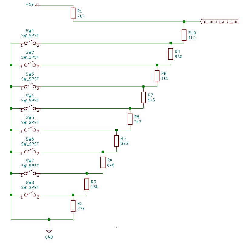
The ADC Values are as follows
- 0-39 fault, 244-255 fault.
- 231 - 243 idle (no switch pushed)
- 40 - 64 button 1
- 65 - 89 button 2
- 90 - 114 button 3
- 115 - 140 button 4
- 141 - 166 button 5
- 167 - 190 button 6
- 191 - 205 button 7
- 206 - 230 button 8
of course it is best to measure with debug when playing with the buttons.
2 buttons
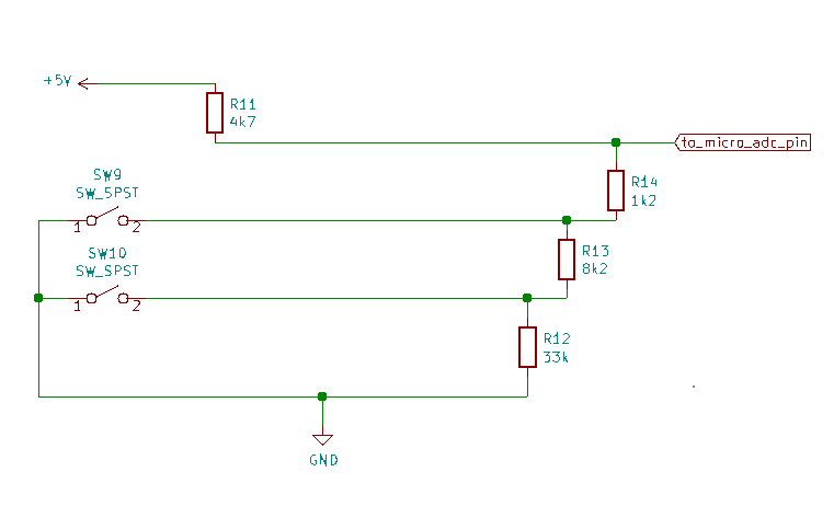
The ADC values are as follows
- 0 - 29, 244 - 255 fault
- 201 - 243 idle (no button pressed)
- 30 - 111 button 1
- 112 - 200 button 2.
Again measure with debug to ensure accuracy
adc_switches.txt · Last modified: 2021/02/14 11:11 by vk3smb