Start of the 6M VK2RWD Build
The time has come to start thinking really hard about the 6M repeater the club has a licence for. We have a licence for 53.5/52.5Mhz. There is much discussion around the internet on how to make Cavities for 6M. Some of the examples are:
- Pieces of LDF 650 made as notches – a set in Tassy somewhere
- Modified VHF low band full length cavities (about 5” tall) – VK3RGV (I know I found them for the shep club).
- Commercially built for 6M. $$$$$$
I have had in my possession now, for nearly 15 years (Back when I was going to build the 6m repeater for AWARC (TCREC back then), before my departure from an unhealthy organisation). I have been hanging onto them for this moment.
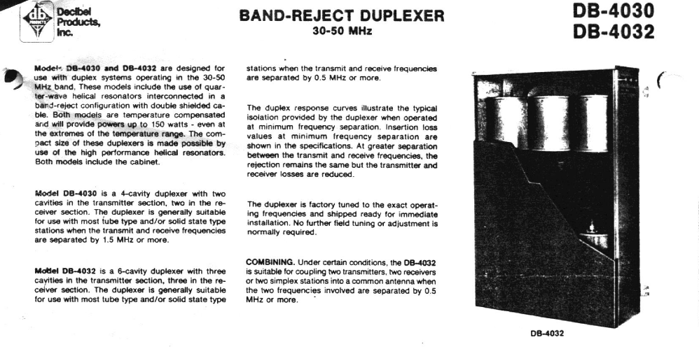
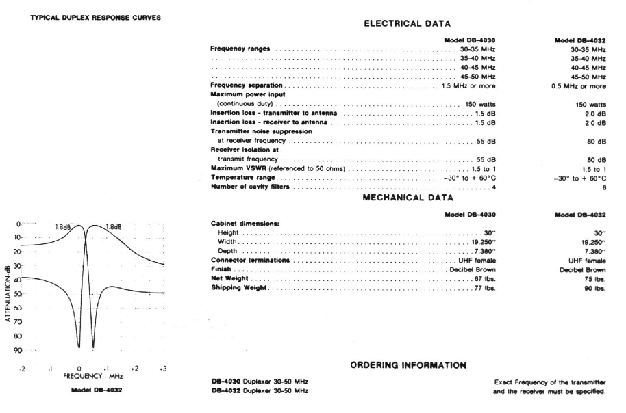
The DB4032 cavities I have came as a 35 – 40Mhz set. They are suited to a separation down to 500khz, with 2dB insertion loss. At 500khz, the isolation is stated to be 80dB. As received, the cavities were set up for 2 transmitters and one receiver into one antenna, and it was missing some coax.
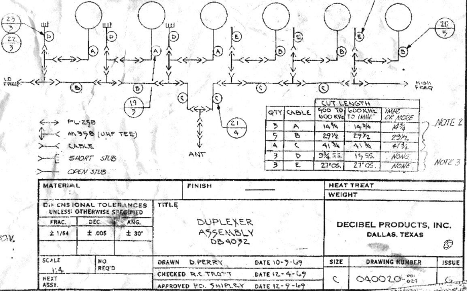 Finding an old photo of what the interconnect cables are supposed to be for a full duplex duplexer I re-arranged the cavities to suit. See Image 3. Drawn in 1969…..
Then came the task to modify them to suit 6M. I set up a jig to cut the helix filters at ½ a turn at a time. This raised the resonance of the cavities towards 6m. HOWEVER, it also completely wrecked (lowered) the “Q” of the cavity as well. So, I had to start modifying the stubs as well to attempt to keep raise the “Q” again.
After a lot of trial and error, I ended up with a cavity that showed similar “Q” to the original design, AND was centred at 53.750 for the high pass, and 52.750 for the low pass. I ended up removing 3 ¼ turns from the helical coils in the cavity (giving me 7 ¼ turns), and ended up with Coax Stubs between 500 and 550mm long.
 With the pathetic leads I was using to test the cavities (some old rg58) with the right ends already on them, I had just on 1 dB of loss through them. I Could have zero'd out the analyser to compensate, however, it was fine for what I was wanting to see.
Tuning cavities is a black art. You start from one end and work your way across the cavities. However, the moment you touch the next one, the first one moves out of tune again… These cavities are relatively simple.. They are only Notch filters configured as high pass and low pass, unlike the cavities on VK3RWO, they are pass/reject cavities, meaning there is a passband that has to be set, and then go back and sort the notch out… 12 Adjustments that all interact again….
I have been playing with cavities for years, and know that if I do this to the next one, the first one does that, so therefore, I need to detune this to compensate for that, and keep all that in my head for 6 cans that all interact. Its just experience that allows me to do that.. Its not something that can be taught.
This is why there is NO intermodulation or de-sense on VK3RWO 2M or 70cm, nor on VK2RWD. Perhaps I need to give the AWARC guys a hand to sort out VK2RAY…….
So after 2 hours of playing, adjusting, playing and adjusting, I got a pattern on the spectrum analyser that I was happy with.
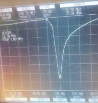
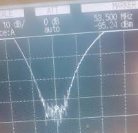
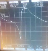
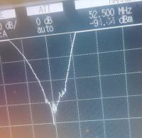
As you can see from photo's 1 and 3, keeping the “Q” nice and high gives the cavities a really steep curve from pass to notch, and allows us to have a 1Mhz split. I could play around with the matching a little more, particularly on the high pass, and achieve a lower insertion loss and 90dB of isolation, however, I would only gain 1 dB at the other end, and that is nothing in reality. I would rather have isolation into the noise floor and slightly higher insertion loss. I am not wasting half a day or more over 1dB….. I'll let Gary worry about that..
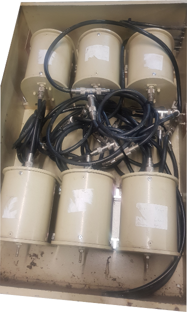 So there it is, a full set of cavities to suit our 6M repeater, that wont take up half of the hut to install them. Here's hoping we can get the whole plot installed for the summer of ducting.
With the holes in the cabinet plugged, and all the interconnect cables secured, here is what the finished product looks like. Perhaps I should sit down and make a folded dipole for 6M too.
