This is an old revision of the document!
Receiver
The Idea
Using Phil's idea, A PRM80/FM828 Hybrid VHF high bandreceiver has been made.
The idea being, use the reliable crystal controlled oscillator of the last 40ish years with a current day amplified front end, shoved into a double balanced passive mixer at a high level then use a 21.4Mhz IF amp at 10.7Mhz meaning more gain.
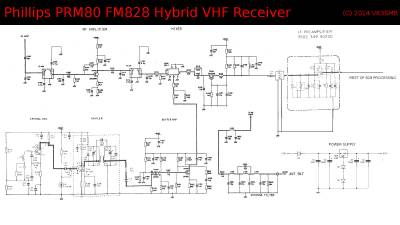
The schematic shows, from the PRM80 I have used:
- antenna filter
- front end
- mixer
- buffer amp, and
- IF amp.
From the 828, I have used
- Crystal oscillator
- tripler,
- IF preamp and
- the rest of the FM828.
The Power supply is a simple voltage reg.
This whole receiver draws 20 mA. so far.
The Hardware Part
=Dissecting the boards=
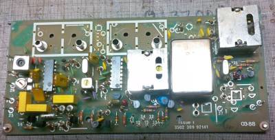
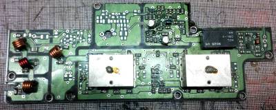
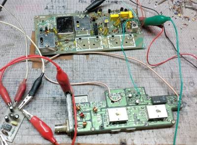
Pictures speak louder than words, but basically the two receivers have been stripped of any component not needed to stop any chance of intermod from something not connected.
Hooked up
Upon hooking it up (and forgetting something - thanks Phil), I tested it at 163Mhz as thats where I had crystals for. My service monitor generates signals down to -140dBm. I could still hear the tone down at that. So plus 1 for sensitivity.
Tuning the Front end
After the sensitivity test was good. Time to tune it for 2M. On the IFR2398, I set the marker at 147.800Mhz and shoved the tracking generator in.
Shown in the picture, there is 10dB roll-off at +- 3Mhz from centre and that the whole plot is only 20Mhz wide to the noise floor. 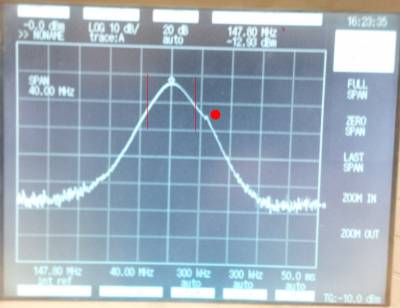 The red dot is showing a blip on the rolloff curve. that is the IF frequency from the crystal I was using. (152Mhz odd).
Mixer
Measuring the signal from the tripler, and then after the buffer amp, the buffer amp is an increase of 30dB. Very high level mixing!
Now need a correct crystal!
IF Bandwidth
It has been decided to use a +-7.5khz bandwidth filter on the front to narrow down the bandpass of the IF. This will help with lower level signals (by decreasing the BW we are also decreasing the noise floor, hence, adding more to the sensitivity and lessening the chance of desense).
Construction
Documentation for reference
Transmitter
The idea
The FM828 Transmitter is phase modulated. this is shitthouse to try and get CTCSS to work correctly and does not sound as nice at the other end.
I propose that we modify the TX for frequency modulation. I am going to rough out a rough circuit diagram for this to happen.
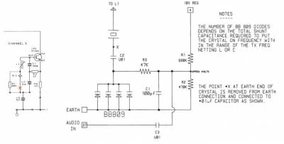
Basically, we need to feed buffered audio into the crystal oscillator at a low level (effectively 1/8 of the level that would be applied to the LO). My bet is to feed it in via varicap diodes
At the very least, we need to Frequency modulate the CTCSS tone and keep the voice PM.
FM Modulation
Doing a google search to save re-inventing the wheel, I was going to use a PRM80 exciter and the FM828 oscillator, VK6UU had gone to the trouble 20 years ago.
TX Audio Processing
To use this effectively these other two diagrams will need to be used. we only need 3 audio inputs - one from the RX, the ctcss out on COR and an input for the watchdog.
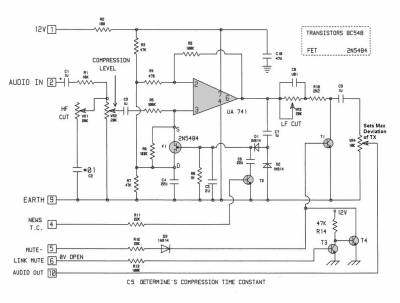
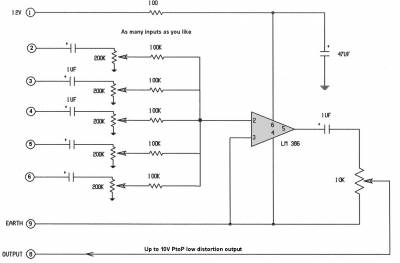
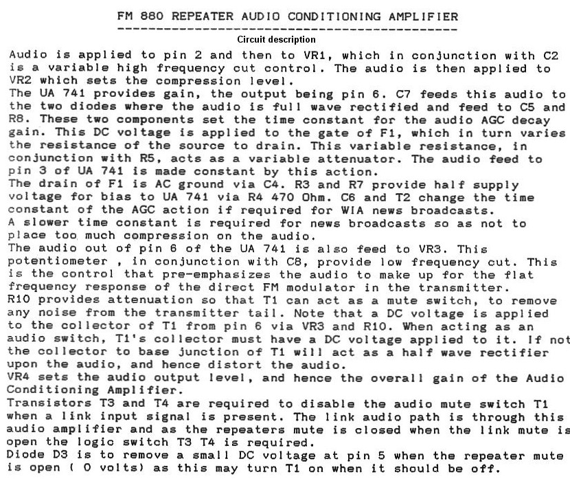
Notes on the audio board
This circuit provides some audio gain control(AGC) along with audio frequency adjustment, both high frequency (above 1khz) and low frequency adjustment (Below 1khz).
Obtaining good audio (sounding like the direct audio) is difficult in a voice repeater for several reasons.
Audio in a repeater is demodulated from being an RF signal (FM) then applied to the repeater's modulator.
All these processes introduce some distortion and frequency response issues.
Also audio levels vary greatly between users, some by as much as 20dB (a lot). The repeater can introduce some audio level compensation so as to reduce this level difference.
However high levels of audio gain control (above 6dB) start to compress users who have levels of back ground noise (eg mobile) and the background noise level starts to e3qual the voice level, which makes for difficult to read audio.
Another issue is a repeater that is linked another (such as the WIA news broadcast) would add another 6dB compression to the previopus repeater's 6dB compression hence the need for the longer time constant that is switched in during WIA news to slow the attack time of the AGC circuit…. ie the AGC action is slower and does not over compress the audio.
This ACG circuit is fairly simple and comples AGC circuits that split up the frequency segments and treat them separately can produce a very good compressed audio that can make a signal sound much louder. The peak to peak is the same but the audio energy between the peak to peak is chockers.
CTCSS Tones
I am suggesting that we fit a subtone to the transmitter only whilst the repeater is receiving a signal in (CTCSS tone in). This means we can use it for linking or control later on.
Control
There needs to be a power down arrangement built in as well. preferably using a transistor rather than a relay 2N3055 comes to mind here.

