Poor Mans Deviation Meter
Here is a deviation meter using the discriminator output of a scanner (any cheap scanner you want to hack into…..). If you search the internet for Discriminator taps you will find listings for nearly every available scanner.
I came about this idea after reading on the internet about how they did it in the “old” days. Basically the discriminator voltage is directly proportional to the carrier frequency error. So what they did was look at the discriminator voltage from a receiver on a cro and set centre freq to centre of the display. Then they would set the receiver 5khz down in freq and transmit again, this time putting a line of masking tape on the screen where the trace was. This procedure was also done 5Khz up from the TX freq. After that they would go back to the centre freq and yell into the mic and adjust the deviation so the trace would not break into the masking tape.
All I have done here is use an op amp as a comparitor and compare a reference voltage to the discrim voltage and show the difference on a meter movement. This is similar to a TODF fox hunting antenna I was reading about (The comparitor bit…).
Please excuse the rudimentary scribble I call a diagram. One day I will enter it into a drawing program and tidy it up
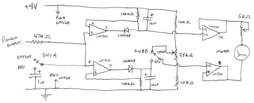
- Switch 1 is a dpdt switch.
- The meter movement is a 0 - 50uA meter, Jaycar P/N QP5012, with a 30kohm resistance.
- You need a very regulated and filtered 8V supply. I chose 8v to allow for 13.8V power supplies that arent really regulated.
Setting it up
- Set the switch to the offset position, transmitting a carrier on the centre frequency.
- Adjust the 25khz pot for a near centre reading on the needle.
- Transmit 5Khz either side of the centre freq and see where the meter ends up. What you want here is a 0 reading on -5Khz and a FSD reading at +5Khz. Play with both pots to achieve this.
- Flick the switch to Dev and you should see the needle sit on 0 with a carrier and move with audio.
I have used this to adjust all my radio's, It will show subtones ok. The version I built has been compared with a Marconi 2955 and gives nearly identical readings. 10uV is 1Khz Deviation. I have found that it is needed to be adjusted slightly between summer and winter.
I scanned in the meter movement background and re-wrote the numbers to reflect deviation. I also added the centre freq mark (its a little above centre on my scanner) to show freq error. I have been able to test other amateur's frequency error and deviation over air as so long as there is a full quieting signal entering the scanner. (Something my Marconi cant do….). Yelling instructions over 70cm to get over his whistling, I was able to assist in adjusting a fellow amateurs deviation on 2m.