Table of Contents
PRM80 Airband
The Phillips/Simoco prm80 radio has proven itself to be a great performer on the 2M and 70cm amateur bands, particularly when dealing with pager interference, and there is quite a few being used as “High Power” UHF CB's. They have up to 160 channels, software programmable, and too many options to list. There is also an E Band version of this radio that has finally been converted to 6 metres.
Now there is an AM Aircraft Band modification for them…..
I am not a writer by any means, nor am I an RF engineer, so bear with the grammar and if you have any suggestions or changes please contact the author. In this article I will show how to convert the A band Prm80 to the Aircraft band using garden variety Jaycar, Dick Smith and Altronics components. While inside the radio it is probably not a bad idea to replace all the surface mount electro caps as well. These can be replaced with SMD tantalum or Jaycar has electro's in the correct size for a replacement.
Parts Required
You need to obtain the following parts:
- M4x0.5 x 12mm F29 or F16 slugs (DSE R5030)
- Ham version of the Firmware
- 5.6pF Ceramic Capacitor
- .001uF poly Cap
- 1uF electro Cap x 2
- 82k resistor
- 10k resistor
- 330k resistor
- BC548 NPN transistor
- Bat46 Diode
Hardware Mods.
This modification is no where near as invloved as the 6m conversion. Basically, the TX sections are ignored as we, as amateurs are not permitted to use the airband, the front end is modified, the RX VCO and the Audio path after the mixer. Make sure you have a working Radio before you begin the modification.
The VCO.
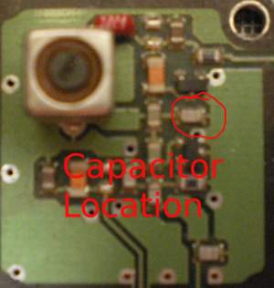
The VCO needs extra capacitance added to allow it to operate on the Airband. Have a close look at the RX VCO. There is a small chip cap mounted where the vacant pads are located in the E band version. On the receive VCO place a 5.6pF smd cap across this cap. See photo 1.
Receiver Front End.
Remove the brass slugs in the 4 front end inductors. Chop 2 of the ferrite slugs in half, I used side cutters and it worked, and screw them mid way into the inductors. See photo 4.
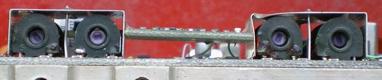 Photo 2: Receiver front end
Making and installing the AM detector
As aircraft transmission are AM, we have to break the FM audio path and install an AM detector.
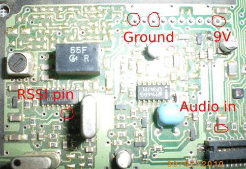 Photo 3: breaking points.
Looking at photo 3 and 4, you need to build the detector circuit and install it. You use the RSSI as the input to the detector, and you remove the Ferrite bead to break the FM audio Path (where audio in is marked on photo 3). I have left the FM part of the board running to allow the squelch circuit to keep operating, hence allowing the radio to scan as well.
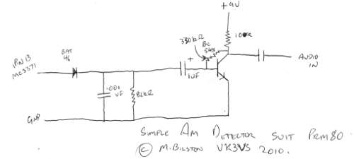 Photo 4: simple as you can get AM detector.
Programming the Aircraft frequencies
To be able to program Airband frequencies you will need to install the Ham version of the Firmware
Firmware information
Work out what frequencies you will want to monitor. Then add 24Mhz to them. The result is the frequencies you will be typing into FPP
Alignment
Parts of this procedure has been extracted from the Phillips PRM8010 service manual. As a minimum you will need the following test equipment:
- A variable signal generator. You could get away with using the local oscillator on a scanner with a 21.4Mhz IF and program it to 129.4Mhz and some attenuator pads.
- Frequency Counter.
A service monitor would be even better.
- Program a frequency of 108Mhz into the radio.
- Set the radio to receive and using the VCO test point set the voltage to 3.5 volts using the slug in the Rx vco inductor. The reason we want the voltage lower than the nominal 15V is the varicaps on the front end use the VCO voltage to tune, if we set the voltage too high they will not tune.
- Using a signal generator, adjust the slugs in the front end for maximum signal, starting at the antenna socket and working your way towards the front.
- Repeat 3 twice more.
- Adjust slug for maximum audio output where you broke the fm audio path (photo 5)
- Disable signal generator, set squelch level to 2 from the front panel, adjust the trimpot circled in photo 5 to allow squelch to mute.
- Measure the RX VCO frequency (after the buffer) and adjust the slug near the reference crystal to a freq of 129.4Mhz (photo 6)
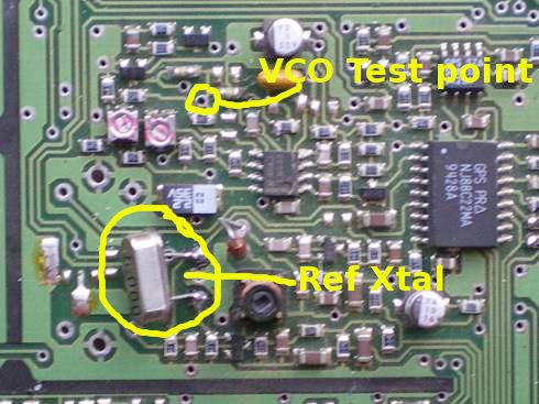
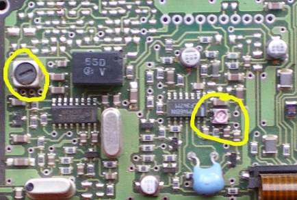 Photo 5 and Photo 6
You should now have a very sensitive and stable AirBand prm80 for minimal cost and a winters afternoon!
Have Fun
Disclaimer
While all information in this document has been tested by myself, I offer no liability for any damage caused by using the information within. This Document is Copyright and remains the property of Matt Bilston, VK3VS. I give my permission for this document to be published in Amateur Radio, and the similar publications in NZ, UK and USA so long as the original content is not modified in any way other than formatting for the magazine. Remember to identify the case in some way that it has been converted to the airband should the radio end up in commercial hands again. It would also be a good idea to disable the TX.
Obtaining parts
It looks like Dick Smith no longer stock the ferrite slugs required. I am going to try and get a source of them. If I can they will be available from me