This is an old revision of the document!
Table of Contents
E Band 6 Metre Conversion
An earlier version of this Article is in the July 2011 Amateur Radio Magazine. The Phillips/Simoco prm80 radio has proven itself to be a great performer on the 2M and 70cm amateur bands, particularly when dealing with pager interference, and there is quite a few being used as “High Power” UHF CB's. They have up to 160 channels, software programmable, and too many options to list. There is also an E Band version of this radio that many have dreamed of using in the 6M amateur band for over a decade however so far this has not been achieved, so much so that they are being thrown out……
Until Now
I am not a writer by any means, nor am I an RF engineer, so bear with the grammar and if you have any suggestions or changes please contact the author. In this article I will show not only how to convert the E band Prm80 to 6 metres using garden variety Jaycar, Dick Smith and Altronics components, but the processes, formulas and errors made during the R&D process. This modification is more than just plugging a piece of commercial radio equipment into a computer and saying “I modified a commercial two-way to the ham bands…”. Every part of the board dealing with 6 metre frequencies needs to be modified in some way. While inside the radio it is probably not a bad idea to replace all the surface mount electro caps as well. These can be replaced with SMD tantalum or Jaycar has electro's in the correct size for a replacement.
Parts Required
You need to obtain the following parts:
- M4x0.5 x 12mm F29 or F16 slugs (DSE R5030)
- 1mm enamel covered wire (Jaycar WW4022)
- .8mm enamel covered wire (Jaycar WW4020)
- 8Mhz Crystal (Jaycar RQ5287)
- SMD Caps, Package 0805 (or you could use ceramic caps), in the following values:
- 12pF (altronics R8527)
- 33pF (altronics R8524)
- 220pF
- 180pF x 2
- 56pF x 4
- 39pF
- 47pF (altronics R8548)
- 22pF (altronics R8536)
- Ceramic Caps (or SMD Caps if you can find big enough ones to handle the grunt) in the following values:
- 470p
- 390p
- 270p
- 100p x 2
- 68p x 2
Hardware Mods.
The RF board will have to be removed from the chassis to complete the modifications. Photo 1 shows the area's of the board which will need modification. Please note this photo is of the prototype and there is extra cuts in tracks and very messy component placement as the work was done from the top side of the board while still in the chassis to quickly see the results of the change.
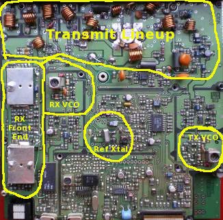 Photo 1: Prototype 6M RF board
VCO's.
Both VCO's require modifying to allow them to operate at the frequencies needed. Have a close look at both VCO's. There is 2 vacant solder pads for capacitors on each VCO. One is linked to ground, the other connects to the inductor. On the receive VCO place the 12pF smd cap on these pads and the 33pF cap on the transmit VCO. See photo's 2 and 3.
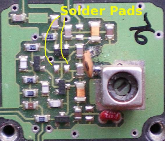
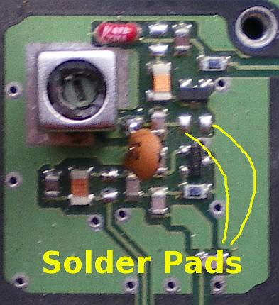 Photo's 2 and 3: TX VCO and RX VCO
Receiver Front End.
Remove the brass slugs in the 4 front end inductors. Chop 2 of the ferrite slugs in half, I used side cutters and it worked, and screw them mid way into the inductors. See photo 4.
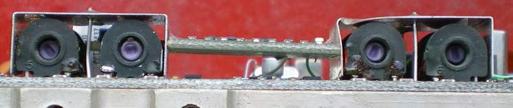 Photo 4: Receiver front end
PA lineup.
Wind yourself the following coils:
A 1mm wire, 4.5 turns, inside diameter 3.5mm and 5.5mm long, need 2 of these. B 1mm wire, 6.5 turns, inside diameter 5.5mm and 7.6mm long, need 4 of these. C 1mm wire, 2.5 turns, inside diameter 5.0mm and 3.3mm long, need 1 of these. D 1mm wire, 1.5 turns, inside diameter 5.5mm and 2.2mm long, need 1 of these. E 1mm wire, 3.5 turns, inside diameter 5.5mm and 4.3mm long, need 1 of these. F 1mm wire, 5.5 turns, inside diameter 5.5mm and 6.5mm long, need 2 of these. G 0.8mm wire, 5.5 turns, inside diameter 6mm and wound tightly, need 1 of these. H 1mm wire, 0.75 turns, inside diameter 6mm, need 1 of these.
Replace the coils as per photo 5. with the exception of G, they should be mounted 2mm from the circuit board. G will need to be closer so it fits under the lid.
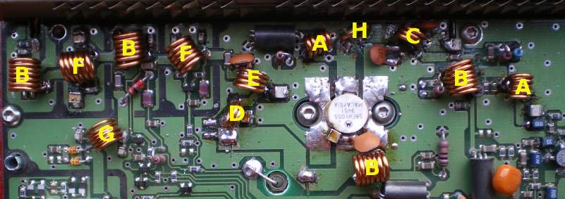 Photo 5: Inductor changes.
To fit Coil H, you need to cut the strip line between the driver and the PA and install it there. About 5mm closer to the driver from where I have put it is best, however you need to keep in mind mutual coupling between it and coils A and/or C. You can also drill 2 holes in the board to allow it to be through mounted for strength when operating in mobile conditions. You will need to clear out some earth pad on the other side of the board though.
Also note with this photo (photo 5), there is a ceramic cap on the collector of the PA. This is a no-no as there could be extra inductance with the leads. This is a junk box prototype!
Photo 6 shows the correct mounting detail for Coil H.
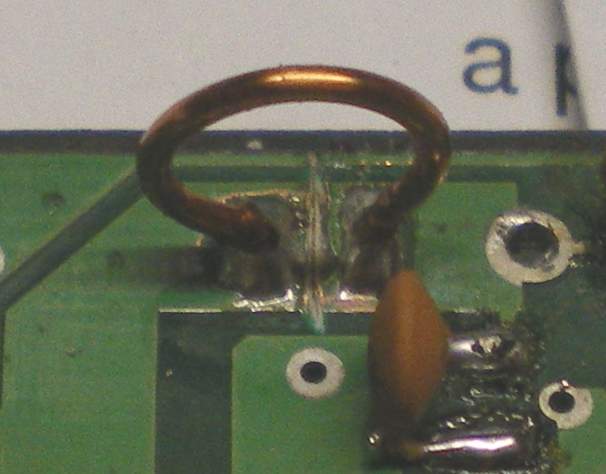 Photo 6: Correct mounting detail for coil H
There are 17 Caps that need changing:
- 180pF was 120pF
- 270pF was 180pF
- 470pF was 330pf
- 100pF was 47 and 68pF
- 390pF was 270pF
- 56pF was 39pF
- 39pF was 27pF
- 68pF was 47pF
- 47pF was 33pF
- 22pF was 15pF
- 220pF was 180pF
Replace the Caps as per Photo 7.
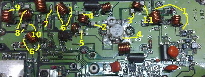 Photo 7: Caps that need changing
You may find, as I did, that adding the caps from a rubbish A9 board to the caps that need to be changed here will give you the values you need. Ignore the trimmer capacitors in photo 7, these were installed during the R&D phase….
Using the Caps available on the board:
Move Caps 2 & 11 to positions 1 Move Cap 5 to position 2 Move 1 of Cap 6 to position 7 Move cap 10 to RX VCO (close enough to 12p) Move cap 9 to TX VCO Move 1 of Cap 8 to position 9
From a junky A9 board, you can get two 68pF large SMD caps from under a loop of wire at the centre rear of the board.
8025 and 8030 users.
See the Firmware information page then program your frequencies and then come back to the alignment section below.
8010 and 8020 users proceed from here
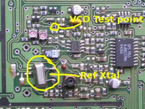
Remove the 10Mhz reference crystal and replace it with the garden variety 8Mhz crystal. Ref Photo 8
Programming the 6M frequencies
Here is the part that has had everyone stumped for over a decade…..
Programming the frequencies is not as straight forward as you would like. The transmit frequencies are easy to calculate as they are the desired frequency multiplied by 1.25. ie 52Mhz multiplied by 1.25 = 65Mhz. Or by doing it correctly, we divide 52Mhz by 5khz and then multiply the answer by 6.25Khz. The programming software will not allow frequencies to be entered below 68Mhz so they have to hex edited. Here is a link to a down-loadable PDF file with the conversions from 6M to E band to TU band and Hex Codes as well.
Programming the receive frequencies is harder to calculate again, as we have to take into account the IF (21.4Mhz). What we do here is take the desired frequency (ie 52Mhz), add the IF to it then divide it by 5Khz. Then multiply that by 6.25Khz and take the IF from it. If you have calculated it correctly your frequency will end up between 70.35Mhz and 72.85Mhz for frequencies between 52 and 54Mhz. These frequencies can be directly programmed into the prm80 software.
Programming hints and idea's
Given the nature of the 6m band, programming one of the buttons at the front to give you access to the mute without turning the radio off and on would be a good idea. Another button with the RSSI programmed in will help with alignment of the receiver. RSSI is received signal strength indicator in Phillips talk.
Alignment
 Parts of this procedure has been extracted from the Phillips PRM8010 service manual. As a minimum you will need the following test equipment:
- A variable signal generator. You could get away with using the local oscillator on a scanner with a 21.4Mhz IF and program it to 74.4Mhz and some attenuator pads.
- A Dummy Load.
- Frequency Counter.
A service monitor would be even better.
- Program a frequency of 53Mhz into the radio.
- Turn the power adjustment to half way.
- Set the radio to receive and using the VCO test point set the voltage to 7� volts using the slug in the Rx vco inductor. The reason we want the voltage lower than the nominal 15V is the varicaps on the front end use the VCO voltage to tune, if we set the voltage too high they may not tune at 6M. Check the lowest frequency of operation (52Mhz) is above 5 1/2 V.
- Set the TX VCO to a similar voltage. See photo 8 for the VCO TP.
- Using a signal generator, adjust the slugs in the front end for maximum signal, starting at the antenna socket and working your way towards the front.
- Repeat 5 twice more.
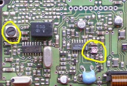
- Adjust slug for maximum audio output (photo 9)
- Disable signal generator, set squelch level to 2 from the front panel, adjust the trimpot circled in photo 9 to allow squelch to mute.
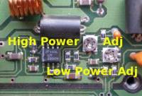
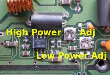
- Select transmit and adjust the power out to 25W max. (photo 10). Check the current is less than 5.5A. (you will need to re-adjust with the lid on).
- While transmitting, adjust the slug near the reference crystal to a freq of 53Mhz (photo 8)
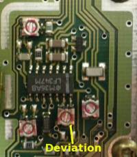
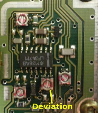
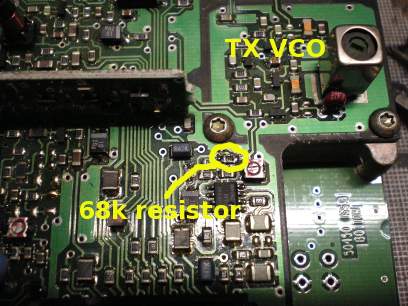
- Adjust the deviation on the control board to 5khz. (photo 11). If you cannot get enough deviation you will need to change the 68k resistor near the modulation balance trimpot to 22k. Ref photo 12. Dion, VK7DB informs me that there is some caps in paralell on the Audio path to the TX VCO. If you remove the first one you come to it drops the capacitance from 33p to 15p and he got 11khz of deviation out of the radio. I will look into the circuit diagram and circle the appropriate cap. He also had to play with the modulation balance after removing this cap. I have also thought about adding another varicap diode to the existing varicap on the Audio path in the TX VCO. I have not played with this however.
 For our English friends, the above procedure will work when based on 51Mhz instead of 53Mhz.
You should now have a very sensitive, powerful and stable 6M prm80 for minimal cost and a winters afternoon!
Specifications I ended up with.
| Frequency | Rx sens (12db sinad) | TX power | TX current |
|---|---|---|---|
| 48Mhz | 1.173uV | Nil VCO lock | Nil VCO lock |
| 49Mhz | 0.268uV | 19.6W | 4.28A |
| 50Mhz | 0.252uV | 21.7W | 4.58A |
| 51Mhz | 0.241uV | 23.5W | 4.87A |
| 52Mhz | 0.241uV | 24.7W | 5.11A |
| 53Mhz | 0.239uV | 25.3W | 5.22A |
| 54Mhz | 0.241uV | 25.1W | 5.23A |
| 55Mhz | 0.271uV | 24.5W | 5.08A |
| 56Mhz | 0.436uV | Nil VCO lock | Nil VCO lock |
| 57Mhz | 0.456uV | Nil VCO lock | Nil VCO lock |
| 58Mhz | 0.472uV | Nil VCO lock | Nil VCO lock |
| 59Mhz | 0.492uV | Nil VCO lock | Nil VCO lock |
| 60Mhz | 0.518uV | Nil VCO lock | Nil VCO lock |
Please note these were measured 25khz up from the frequency as microprocessor noise was evident.
Four of these radios have been built, one by Phil, the others by myself, we both did it with parts from the Junk Box, with the exception of the crystal (I had nearly every value but 8Mhz). Each of the modified radios ended up with similar specifications. These measurements were taken with a Marconi 2955 service monitor.
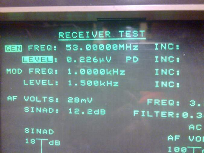
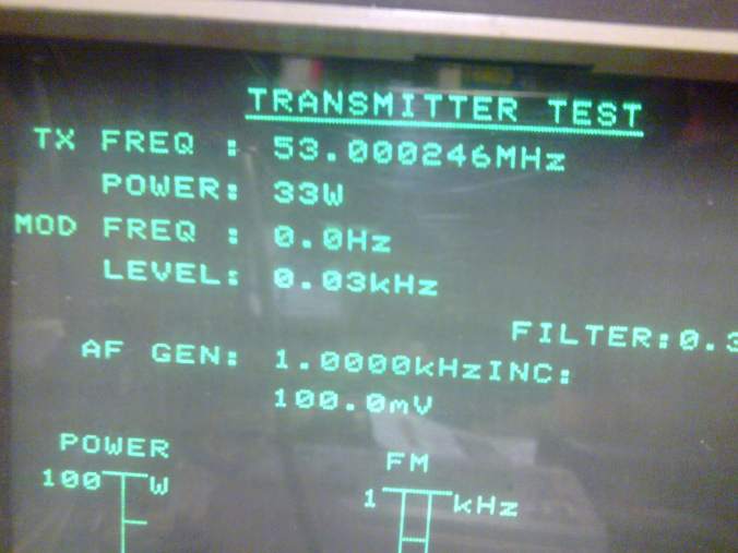 Photo's of the service monitor with one of the “production” units on test.
Errors and Headaches during the R & D Phase
Many hours of playing has gone into this, particularly trying to work out how to break the magical 58Mhz barrier.
- I went to de-compile the firmware in the pmr8030, after seeing the output, I forgot that idea straight away.
- I thought about putting a frequency tripler between the pll and the pre-scaler and programming the radio to 156Mhz odd. This was shot down in flames with the availability of something small enough to fit in the radio shield and stability was also going to be an issue.
- I found some 40/41 pre-scalers. This worked ok at 52Mhz, but due to rounding errors in my mathematics, I was out 80Khz at 54Mhz. And the steps were quite an odd value. But with Phil clearing the forest so I could see the trees, I found a simple crystal change would have saved me a heap of work.
- After spending around 6 hours rebuilding the RX front end, changing caps etc, I found I didn't need to do all that, all I had to do was change the slugs from brass to ferrite.
- During TX playing, I've managed to damage 2 PA's as the driver has a staggering amount of gain at 50Mhz.
- After a lot of hair pulling, found out the stripline between the driver and PA is too short, causing it run away when the case was re-assembled due to a mis-match and extra capacitance of the shield.
Problems
If anyone can think of answers to these I'd love to know them.
- The repeater defeat button will not work as the IF offset is different due to the “hacked” programming. If the VCO did lock it would be transmitting above 60Mhz for frequencies programmed in for 53Mhz
- Microprocessor noise is evident at quite a few places on the band.
Thanks to
Jason, VK7ZJA for his excellent and thorough documentation on the Prm80, and for exhausting every other avenue before I got to them. Phil, VK3ELV for his ideas and the re-development of the PA Garry, VK3XYX for his donation of “rubbish” E band RF boards, and
Have Fun
Alternative to changing the reference oscillator
I have finally worked out the Firmware in the PRM8025/30's for a neater conversion, follow the following link to do a firmware upgrade and benefit from less processor noise and “normal” radio behaviour. Firmware information page
Disclaimer
While all information in this document has been tested by myself, I offer no liability for any damage caused by using the information within. This Document is Copyright and remains the property of Matt Bilston, VK3VS. I give my permission for this document to be published in Amateur Radio, and the similar publications in NZ, UK and USA so long as the original content is not modified in any way other than formatting for the magazine. Remember to identify the case in some way that it has been converted to 6M should the radio end up in commercial hands again.
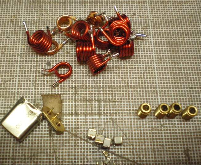
The leftover bits
Obtaining parts
It looks like Dick Smith no longer stock the ferrite slugs required. I am going to try and get a source of them. If I can they will be available from me.
Looking at junk boxes, Appropriate slugs can be found in E band FM900's!!!!!
Thanks to Dion VK7DB, There is another source of Slugs. He informs me that the old Plessey “Bug Eye” Radios have slugs of the correct thread, pitch and material in them.