New Antenna for VK3RWO
Ever since the VK3RWO repeater was installed it has had a VHF High band antenna for the 2M radio. The Antenna was centred on 160Mhz. While this had an exceptable VSWR on 147Mhz, I have always accepted that the radiation pattern has not been that great. At 147Mhz there would have been lobes shooting into the sky.
Whilst this antenna has been performing OK, with the help of Dion, VK7DB I set about manufacturing a new 2M antenna for exactly 146.975Mhz.
The antenna I started with was a 70 – 85Mhz antenna. This antenna was a left over from a decomissioned commercial installation, and given the latest from the WIA and RASA that we would not get any of the 4M band in Australia due to the IARU and the commercial usage in VK, I thought it is time to give it a haircut with the hacksaw.
Dion has a great experience in using MMANA-GAL modeling software. I gave him the radius of the bends and the size of the pipe, and asked him to model it down to 146.975 Mhz.
The answer given was that I needed an end to end of 934mm.
The top element was to come down to the centre line, and the bottom element was to stop short of the centre line by 20mm.
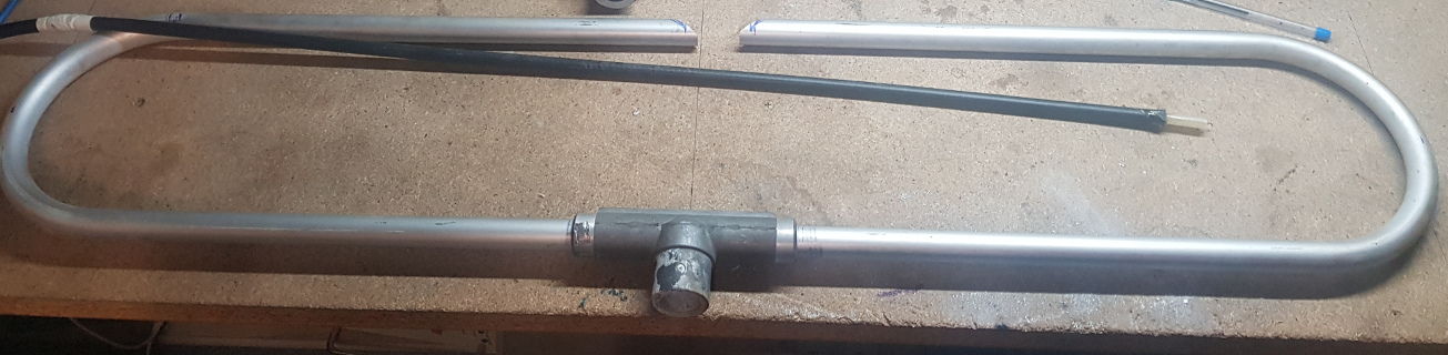 Photo 1: Cutting all complete….
The next hardest part was matching the antenna. As we use 50 Ohms to the radio, and a Dipole is 292 Ohms (4 x 73ohm), a matching stub is needed.
So an electrical quarter wavelength of 120.8 Ohm coax is needed. As it happens, The commercial guys have been using RG-63 Coax for years to match dipoles. This cable is 120 to 125 ohm depending on which datasheet you look at. It also has a velocity factor of .84.
So. I needed a piece of RG63 that is 428mm long.
Fortunately, the folded dipole I cut up had a piece around 700mm long. Instead of just cutting to maths, I have the fortunate pleasure of using an AA-1000 antenna analyser. With this I put the stub onto the analyser, and using the resistance (R) and reactance (X) graph, I was able to shorten the stub until the R and X crossed paths. This was the optimum length
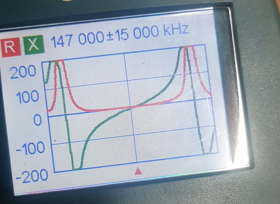
Photo 2: The screen of the AA-1000
So after finding the correct length, I had to thread it back into the dipole and attach the braid to the top element and the centre conductor to the bottom element
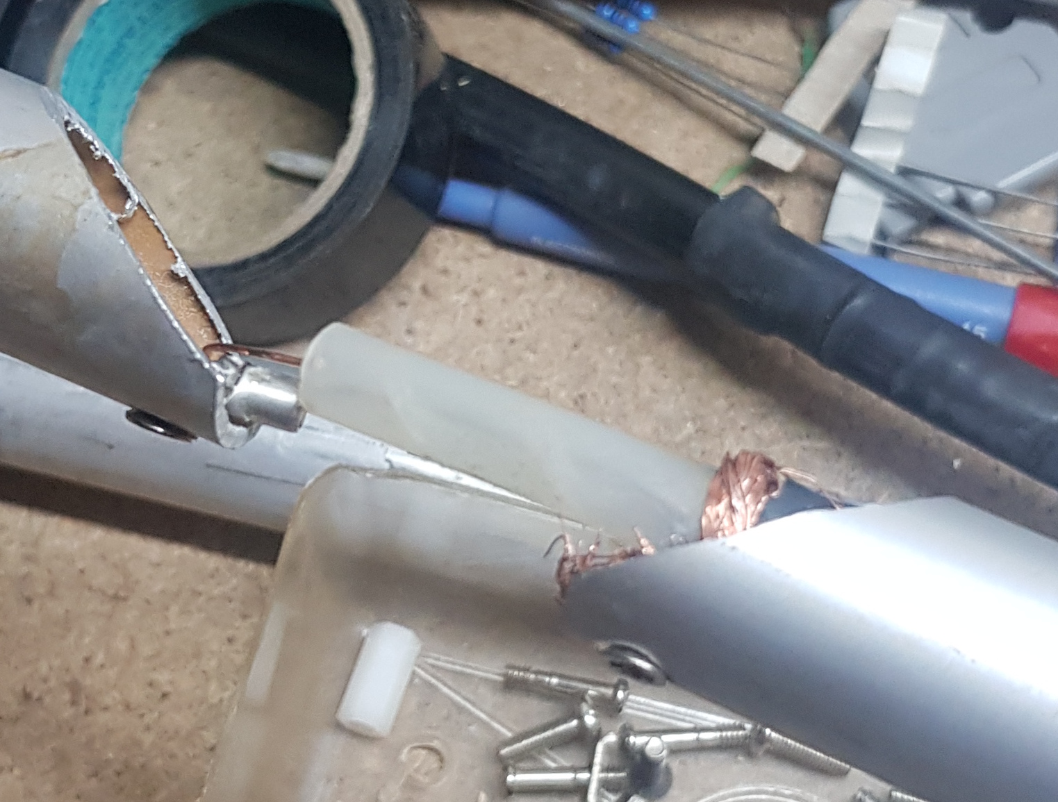
Photo 3: The terminating of the coax.
So after gluing a piece of pvc pipe over the termination point and covering it in heavy walled heatshrink (it also has glue in it), it was time for a test.
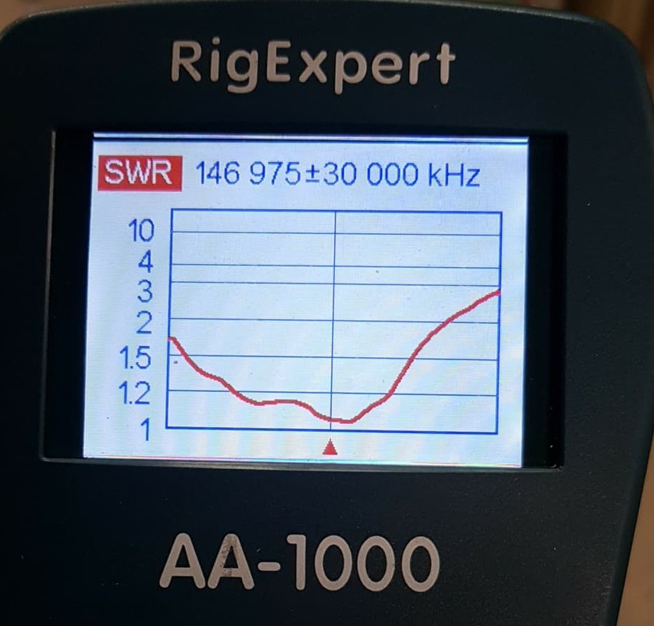
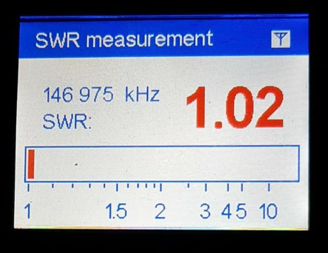
Photos 4 and 5: Screen shots of the AA-1000 showing the resonance of the antenna.
Now All I have to do is take the antenna up the hill and install it onto the repeater.
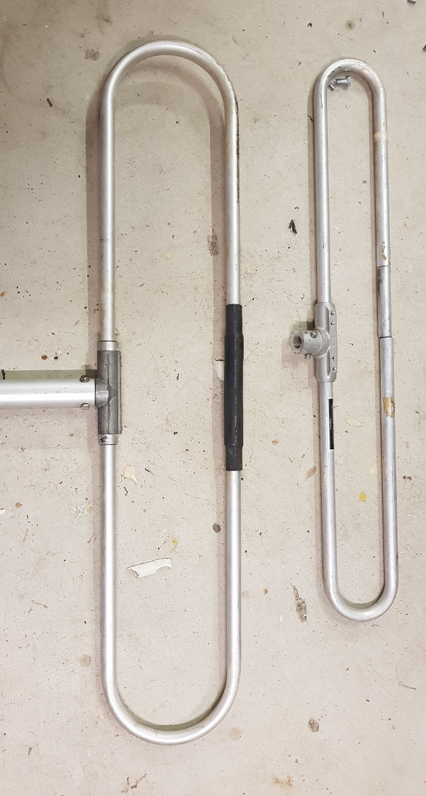
Photo 6: The finished product. It is a monster compared to a VHF Highband one